Structural CAD
I developed nose-cone and recovery-interface CAD and reviewed the body, fin and motor-region structural interfaces with the team.
Structural design and simulation for a student rocket targeting a simulated 4,000-foot apogee
As Structures Lead, I worked on the nose-cone geometry, shoulder/body fit, recovery attachment and structural integration. Our team manufactured and ground-tested Daedalus, but never launched it. The 4,086-ft apogee is a simulation prediction; the 275 N eyelet comparison evaluates a conditional recovery case, not a measured deployment.
I compared an original-style rounded eyelet with a wider concept in matched SolidWorks studies to evaluate the recovery load path. The original hole and root dimensions were unavailable, so those dimensions are stated assumptions. Daedalus hardware was manufactured and ground-tested, but never launched.
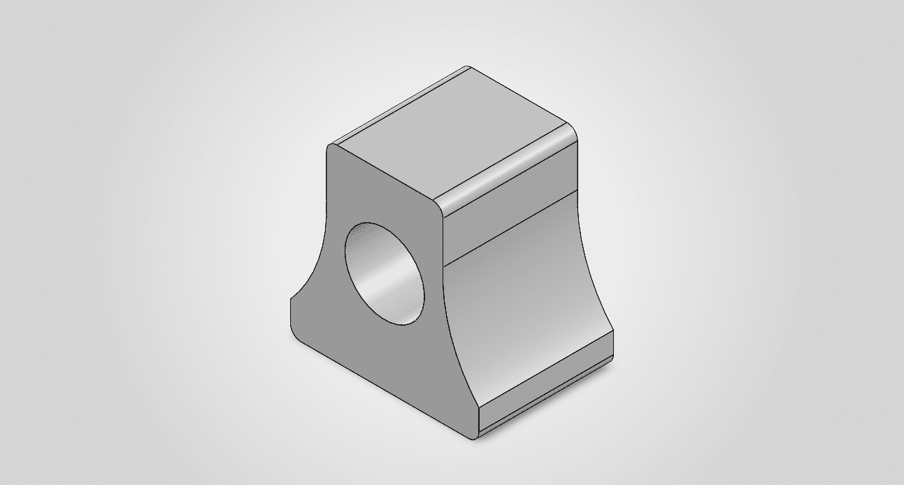
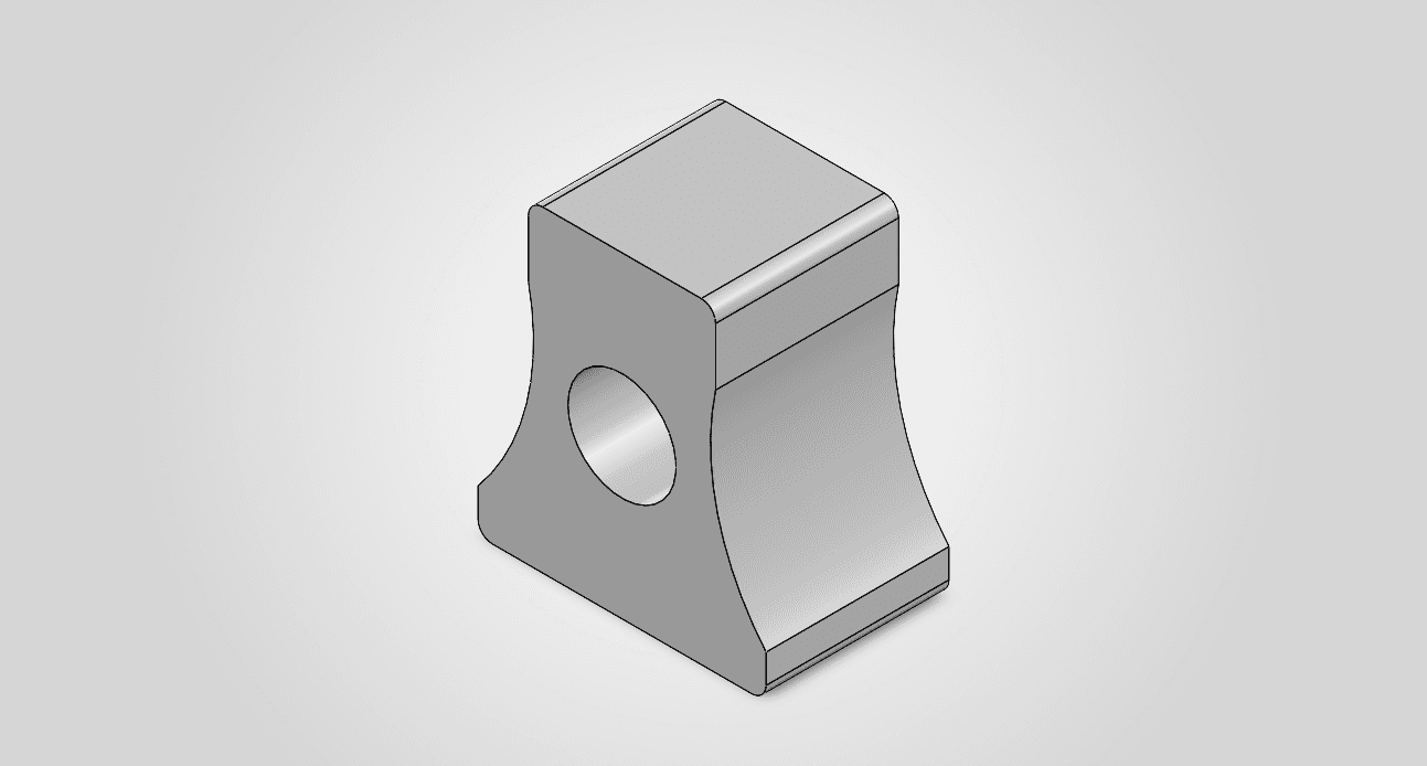
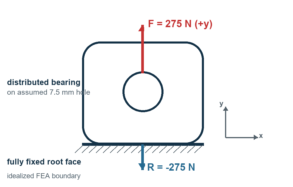
The assumed 7.5 mm hole carries a distributed +Y bearing load; the fixed root supplies the opposing reaction. The 275 N case is a conditional structural screen, not a measured deployment load.
D = 0.6096 m; assumed ρ = 1.225 kg/m³, CD = 1.75, opening multiplier Ko = 2, and separate structural multiplier Ks = 2. For 1.0 and 2.0 s hypothetical delays, the corresponding screens are 120.4 and 481.7 N.
The reference radial nose wall is (1.400 − 1.300)/2 = 0.050 in. Its reference body and shoulder diameters imply zero nominal clearance. I propose finishing the shoulder near the measured bore +0.001 in interference, then accepting it by 15–20 N extraction and ≥35 N ejection tests.
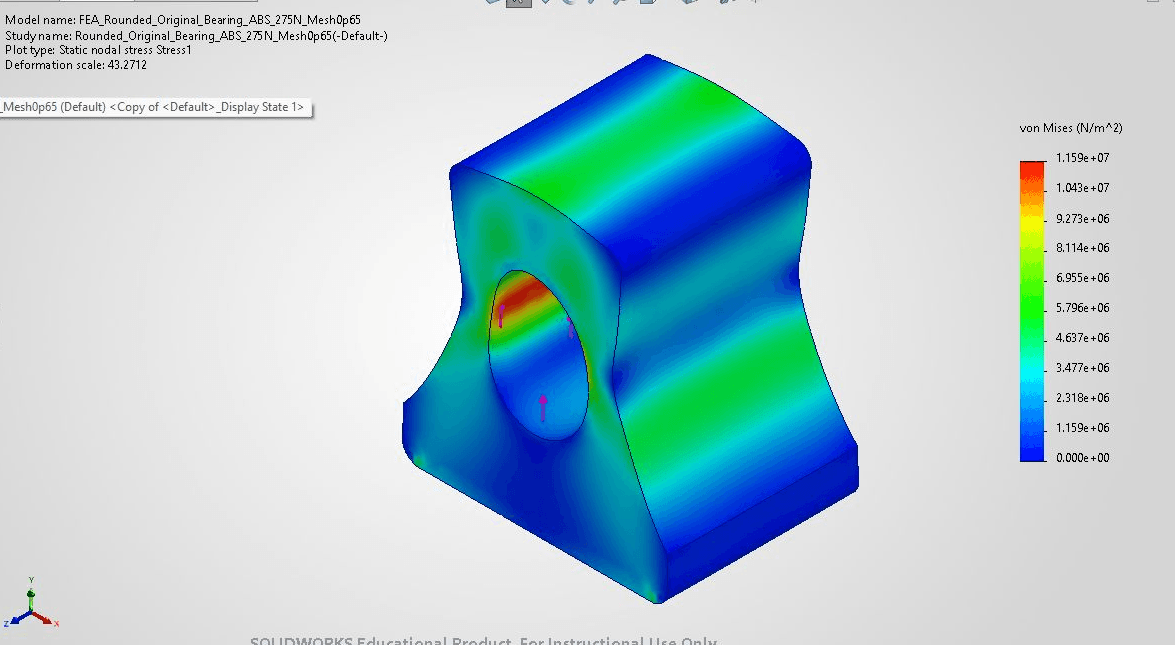
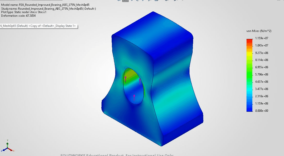
At the matched 275 N, 0.65 mm ABS mesh target, peak von Mises stress fell from 11.591 to 8.869 MPa (23.5%), and maximum displacement fell from 0.04138 to 0.03299 mm (20.3%). Reactions balanced 275 N within 0.002 N. This supports prototyping the wider eyelet, not release as a flight-ready anchor.
The earlier 174.59 N series refined each design from 1.20 to 0.65 mm; the 275 N final studies used the 0.65 mm target. Peak stress was not perfectly monotonic with mesh, so the reduction is a screening trend. The added width and top ligament use more material. Real pin contact, root-to-nose attachment, off-axis loading, printed PLA strength, and deployment dynamics remain unvalidated.
Project Daedalus challenged our team to design a compact rocket that could approach a simulated 4,000-foot apogee while remaining stable, manufacturable, and recoverable. The structure could not be designed independently from the rest of the vehicle.
Changes to the nose cone, fins, avionics packaging, motor placement, or recovery hardware affected total mass, center of gravity, center of pressure, drag, assembly, and deployment. I worked primarily on the mechanical and structural side: structural CAD, component interfaces, manufacturing considerations, tolerance checks, and early simulation.
I coordinated structural interfaces with teammates responsible for avionics and propulsion. The avionics design and packaging were their work.
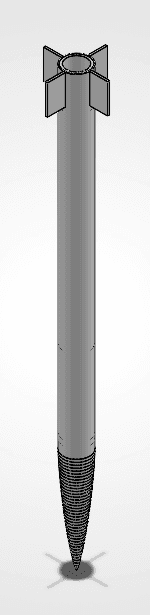
I developed nose-cone and recovery-interface CAD and reviewed the body, fin and motor-region structural interfaces with the team.
I worked on the nose-cone geometry and its interface with the body tube. The part needed to support the aerodynamic profile, fit the available 3D printer, maintain adequate stiffness, and separate during parachute deployment.
I considered printer limits, material selection, wall geometry, infill, component clearances, and friction-fit behavior before fabrication. Small dimensional errors could prevent assembly or interfere with recovery deployment.
I worked with teammates responsible for avionics and propulsion to understand packaging, mounting, access, and wiring requirements. That communication helped keep mechanical changes from creating problems for another subsystem.
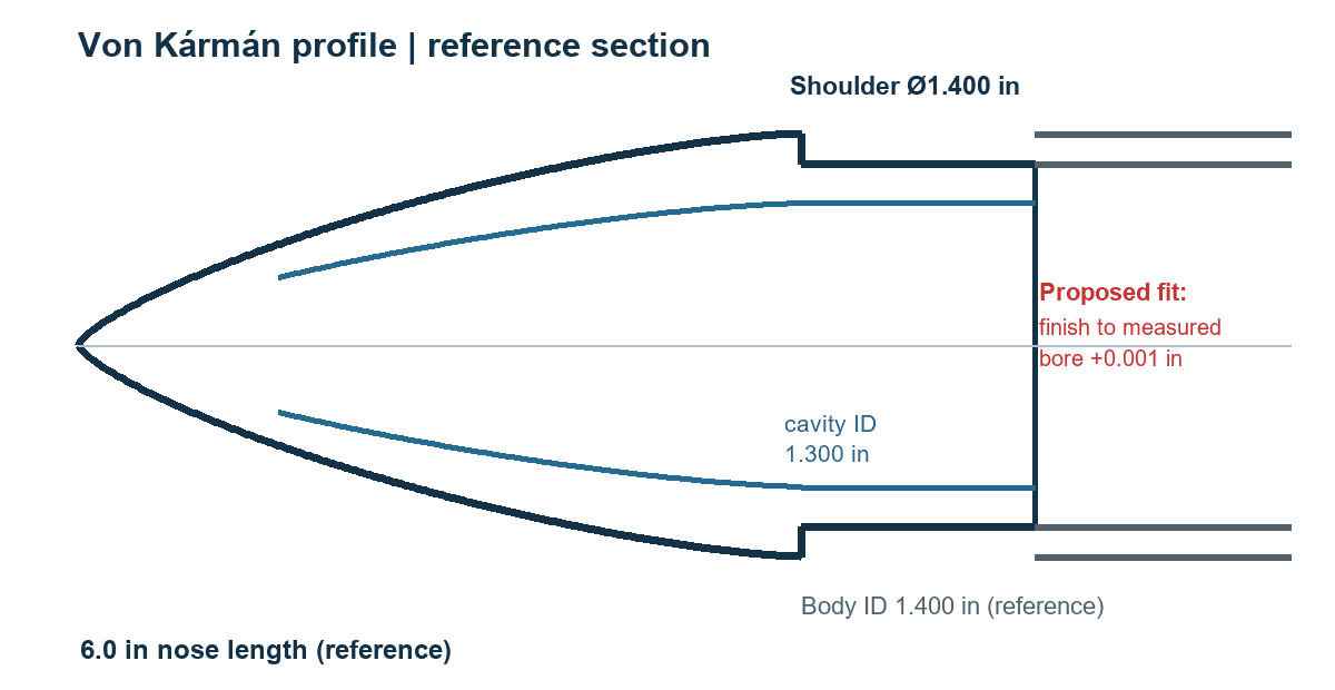
The nose cone had several jobs at once. It defined the leading aerodynamic geometry, added structural mass near the front of the vehicle, connected to the body tube, and separated as part of the recovery sequence.
The Von Kármán profile gave the team a practical aerodynamic shape for the available length and diameter. The design also had to fit within the available printer volume and avoid geometry that created unnecessary printing difficulty.
Using a high infill increased rigidity, but it also increased forward mass. That mass affected the vehicle's center of gravity, which meant the nose-cone design had to be evaluated in the context of the complete OpenRocket model.
The shoulder used a friction-fit connection with the body tube. The fit needed to remain secure during handling and ascent while still allowing the recovery system to separate the nose cone near apogee.
The complete vehicle mattered because each subsystem created structural interfaces. I did not own every subsystem, but their packaging and load paths affected the mechanical design.
The propulsion, recovery, and avionics systems are included to show the interfaces and constraints that affected my structural work. They were collaborative team systems rather than solely my individual designs.
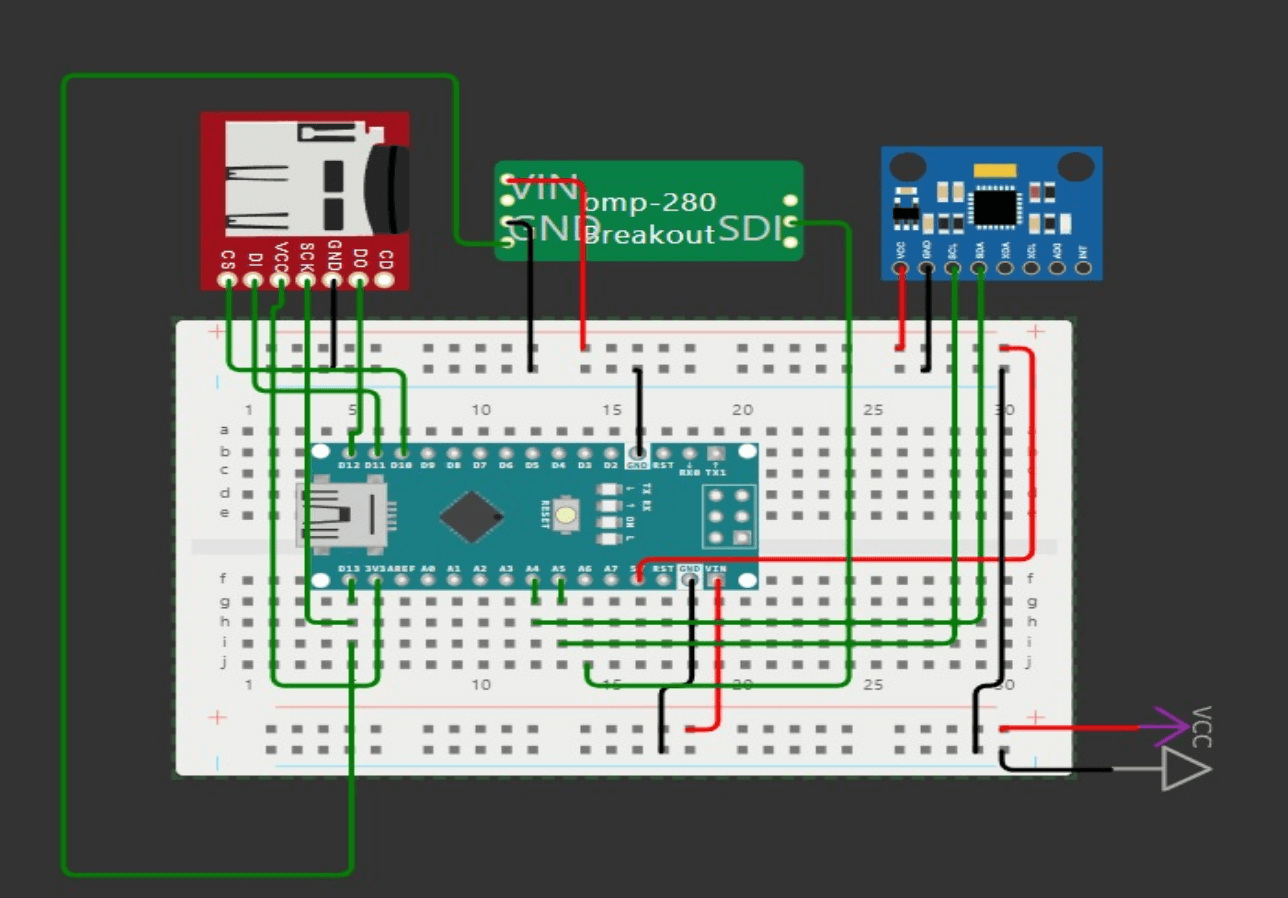
The avionics package affected the mechanical design even though my primary role was structural. The Arduino, pressure sensor, inertial sensor, SD-card module, battery, wiring, and mounting hardware all had to fit within the available internal diameter.
I coordinated available structural space and access requirements with the electrical team. I did not design the avionics bay or package its electronics.
The external geometry influenced drag, but the part still had to fit the available printer, print reliably, and connect to the body tube without excessive post-processing.
Increasing material, infill, or thickness improved rigidity but also changed total vehicle mass and shifted the center of gravity.
The nose-cone interface needed enough friction to remain assembled before deployment without preventing the recovery system from separating it.
Moving the motor, avionics, battery, recovery hardware, or printed components changed the mass distribution. Packaging choices therefore affected both mechanical integration and aerodynamic stability.
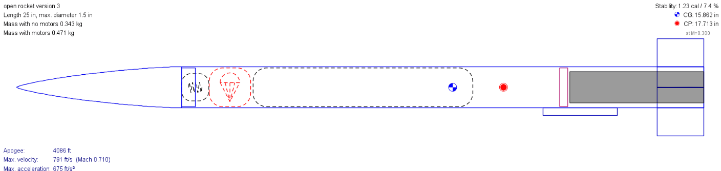
OpenRocket allowed the team to see how structural changes affected the complete flight model. A change that improved one component could also shift the center of gravity, change stability, add drag, or reduce predicted altitude.
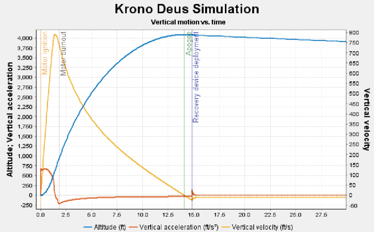
The plots and 4,086-foot apogee are historical CDR predictions, not flight data. The original .ork file was unavailable for this retrospective, so I did not independently rerun or tune that result.
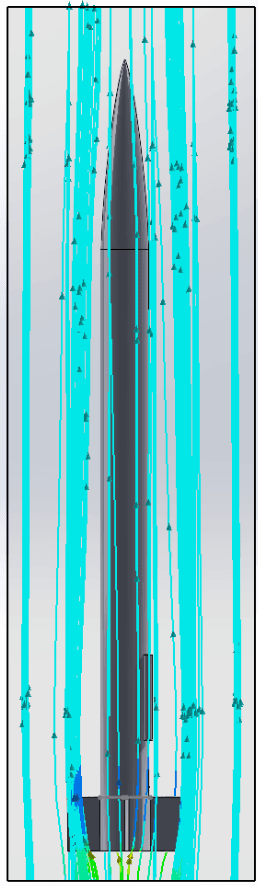
The flow simulation gave the team an early qualitative view of the pressure field and flow paths around the rocket geometry. It helped us identify areas of the vehicle worth examining and communicate how the external geometry interacted with the surrounding flow.
I treat this as an exploratory design study, not validated computational fluid dynamics. The project records I have do not document enough about the mesh, boundary conditions, turbulence model, convergence, or experimental correlation to claim more than that.
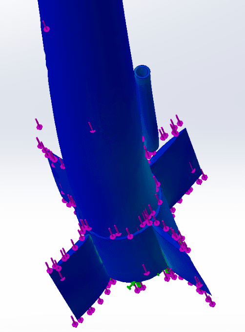
The archived structural image was a preliminary design check rather than formal qualification. Its geometry, material, fixture, and result file are not sufficiently documented for a matched numerical comparison with the new eyelet studies.
The rounded-eyelet comparison uses an explicit, conditional 275 N screen derived from a hypothetical parachute-opening scenario. This modeled load is not a measurement from the rocket.
Defined the approximate altitude target, vehicle envelope, stability needs, recovery approach, motor constraints, and manufacturing limits.
Created and reviewed nose-cone and structural-interface CAD while coordinating subsystem fit with teammates.
Used OpenRocket and preliminary structural studies to review stability, predicted performance, and structural behavior.
Coordinated with propulsion and avionics teammates as their packaging and hardware requirements developed.
Adjusted geometry, fit, material use, and component placement based on integration and manufacturing constraints.
Supported fabrication planning, physical assembly, and team testing activities.
This project changed how I think about mechanical design. A part can look correct in isolation and still cause problems when tolerances, manufacturing limits, wiring, mass distribution, recovery motion, and neighboring subsystems become real.
I learned to check interfaces earlier, use simulation to eliminate weak concepts before fabrication, and evaluate structural decisions in the context of the complete vehicle.
Working with teammates focused on avionics and propulsion also improved how I communicate across disciplines. I needed enough understanding of their systems to design around packaging, access, wiring, mounting, and deployment requirements.
Project Daedalus taught me to connect CAD, simulation, manufacturing, and subsystem communication. My strongest contribution was not a single isolated component. It was making structural decisions while accounting for how the complete rocket needed to assemble, remain stable, package its hardware, and support recovery.